Difference between revisions of "Turtle Sense cable assembly instructions"
Jump to navigation
Jump to search
(Added cable sealing instructions) |
(→Smart Sensor cable fabrication instructions: Add photos) |
||
| Line 48: | Line 48: | ||
==Smart Sensor cable fabrication instructions== | ==Smart Sensor cable fabrication instructions== | ||
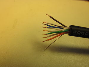
| + | [[File:Sensor_Cable_Stripped.jpg|right|thumb|300px|The sensor cable end stripped and ready for crimp pins.]] | ||
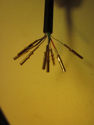
| + | [[File:Sensor_Cable_With_Pins.jpg|right|thumb|300px|The sensor cable end after crimping pins on the wire ends.]] | ||
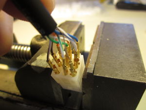
| + | [[File:Inserting_Pins_Into_Housing.jpg|thumb|right|300px|Inserting the pins into the Molex housing.]] | ||
#Cut a 20 ft length of the cable and strip 3/4" of the jackets, as above. | #Cut a 20 ft length of the cable and strip 3/4" of the jackets, as above. | ||
#Remove the soft liner layer from the inside of the bottle cap. | #Remove the soft liner layer from the inside of the bottle cap. | ||
Latest revision as of 13:37, 14 September 2014
Overview
A short length of shielded Cat5e cable is wired to the Comm Board, and a 20 ft length of the same cable is wired to the Smart Sensor board before the boards are cast in polyurethane plastic. A female Molex connector is attached to the sensor cable and a male molex connector is attached to the comm board cable. The Comm PCB and Phone Board is mounted on two wood blocks which attach to the PVC Inside Threaded Pipe Plug.
Materials used
- Shielded direct burial cat5e cable
- Assembled Comm circuit board
- Assembled Smart Sensor circuit board
- Janus Terminus phone board
- SMA female to U.FL male adapter cable
- Cell phone antenna
- 9V battery clip with 12" leads
- Molex 9-pin plug
- Molex 9-pin receptacle
- Molex male pins
- Molex female pins
- 75cc white pharmaceutical HDPE round bottles with screw top lids.
- 1/16" shrink tubing
- 1/2" shrink tubing
- PVC pipe assemblies (see PVC Housing assembly instructions)
- Hardwood blocks (see PVC Housing assembly instructions), qty 2
- #6 x 5/8" Stainless steel sheet metal screws, qty 4
- #6 x 3/4" Stainless steel sheet metal screws, qty 4
- #6 nylon clearance spacer 1/8" long, qty 4
- 5-minute epoxy
- E6000 adhesive
Comm board cable fabrication instructions
- Cut a 20" length of the cable and strip 3/4" of the outer and inner jackets on one end, being careful not to nick the drain wire between the jackets.
- Drill a 9/32" diameter hole in the center of the bottom of a 75cc pharmaceutical bottle, and de-burr the hole with an X-acto knife.
- Insert the stripped end of the cable through the bottom of the bottle.
- Untwist the pairs and straighten the wires somewhat.
- Strip 3/16" of insulation on each wire.
- Crimp 9 gold plated male pins to the wires, preferably with the Molex crimping tool.
- Solder the crimped connections.
- Insert the pins into the Molex receptacle, following the Comm board schematic, page 2.
- Insert the end of the cable through the back-to-back PVC end cap assembly.
- Insert the end of the cable through the 1/4" hole in the center part of the screw-in PVC Inside Threaded Pipe plug.
- Strip 7/8" of the outer and inner jackets on the other end of the cable.
- Untwist the pairs and straighten the wires somewhat.
- Shorten the striped wire of each pair by about 1/8".
- Strip 3/16" of insulation on each wire.
- Place a 1/2" length of 1/2" shrink tubing over the cable. Don't forget this!
- Place a 5/8" length of 1/16" shrink tubing over the drain wire.
- Solder all the wires to the Comm PCB, with the wires coming in on the microprocessor side of the board, with the cable parallel to the board and coming off in the direction of the end of the board. Follow the Comm board schematic, page 2.
- Position the 1/2" shrink tubing piece over then cut end of the jacket, so that any exposed bit of the foil shield is covered, then shrink it with a heat gun.
- Insert the ends of the leads of the 9V battery clip through the PVC Inside Threded Pipe Plug.
- Solder the wires to the Comm board, observing the correct polarity (black=com, red=12V)
Smart Sensor cable fabrication instructions
- Cut a 20 ft length of the cable and strip 3/4" of the jackets, as above.
- Remove the soft liner layer from the inside of the bottle cap.
- Using an X-acto knife, cut out a hole about 5/8" diameter in the center of the liner. Discard the center part.
- Drill a 1/4" diameter hole through the center of the bottle cap, and carefully deburr the hole with an X-acto knife. The cable will be a tight fit in this hole, and any sharp edges can nick or scrape the cable jacket.
- Re-insert the liner into the bottle cap lid.
- Insert the stripped end of the cable through the hole in the bottle cap, going through from the outside of the cap.
- Attach the Molex connector as above, but using a Molex plug and female pins. Follow the Comm board schematic, page 2.
- Strip 5/8" of the outer and inner jackets on the other end of the cable.
- Untwist the pairs and straighten the wires somewhat.
- Shorten the solid color wire of each pair by about 1/8".
- Further shorten the blue, blue-white, green, and green-white wires by about 1/16" This is so that the cable will be centered side-to-side on the Smart Sensor board. If the cable is well centered, it makes it easier to cast the board in the plastic without any corners touching the surface.
- Strip 3/16" of insulation on each wire.
- Solder all the wires to the Smart Sensor board, with the wires coming in on the microprocessor side of the board. The center axis of the cable should be in line with the center of the Smart Sensor board. Follow the Comm board schematic, page 2.
Comm PCB mounting and cable sealing instructions instructions
- Attach the SMA connector of the adapter cable to one of the 1/4" holes of the Comm PCB. The nut goes on the microprocessor side of the board. Tighten it securely.
- Plug the Terminus phone board into the Comm board.
- Attach the U.FL connector of the adapter cable to the phone board, on the connector marked "cell".
- Attach the cell phone antenna to the adapter cable. Tighten it with the antenna paralllel to the long dimension of the Comm board.
- Attach the two wood blocks to the Comm board, using the 4 nylon spacers and the 4 #6 x 5/8" screws.
- Adjust the position of the PVC Inside Threaded Pipe Plug so it is against the wood blocks, and attach it to the blocks with the 4 #6 x 3/4" screws.
- Mix a small amount of 5 minute epoxy and apply it to the PVC Inside Threaded Pipe Plug around the cat5e cable and around the wires. Use just enough to seal off the two holes.
- After the epoxy has hardened, apply generous dabs of E6000 around the cat5e cable, the battery wires, and over the heads of the 6-32 x 3/4" screws. Keep the PVC plug level for a few minutes to prevent the E6000 from running.
- After the E6000 has set, move the PVC battery compartment pipe section up the cat5e cable. There should be about 8" (+/- 1/2") of cable from the PVC Inside Threaded Pipe Plug to the back to back Shallow Flat Caps.
- Mix a small amount of 5 minute epoxy and apply it to the PVC Shallow Flat Caps around the cat5e cable. Use just enough to seal off the hole.
- After the epoxy has hardened, apply generous dabs of E6000 around the cat5e cable on the battery compartment side. Keep the PVC plug level for a few minutes to prevent the E6000 from running. After a few minutes, apply E6000 similarly to the opposite side of the caps.


